|

Teacher: Prof. G. Vossoughi
Laboratory Responsible Mr. Khamseh
Teacher Assistants: Seyed Mohammad Moeini & Rouhollah Khalesi
|
-
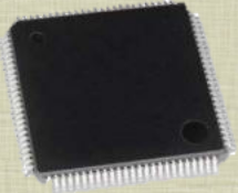
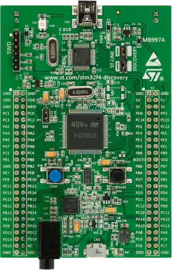
In the mechatronics laboratory we work with STM32F407VGT6 microcontroller where shown in the below.
-
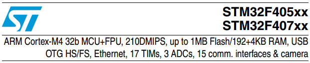
The below pdf files are useful to learn how to use the 32-bit microcontroller family of ARM.
-
In the mechatronics laboratory we work with STM32F4DISCOVERY (STM32F4 high-performance discovery board).
-
The below pdf file is useful to learn how to use STM32F4 high-performance discovery board.

-
All the students who take the mechatronics course should pass the laboratory of mechatronics, because the final project of mechatronics (which likely is control of a mechanical system) must implemented with the discovery board.
-
All the necessary contents for the Mechatronics Lab available on the computers of Mechanical Engineering Department, in the following path:
-
\\mechserver\information for users\Ms\Dr.Vosoughi\mechatronicsLAB
-
Students can find and download Lab program, examples and presentations on the remainder of this page during the semester.

- The first meeting topics:
- Introduction to ARM microprocessors, and ARM microcontroller manufacturers
- Introduction to STM32F407VGT6 Microcontroller, manufactured by ST Micro.
- Introduction to STM32F4 high-performance discovery board
- Introduction to Embedded Development Tools: Keil, ...
- The second meeting topics:
- Introducing STM32F4xx_StdPeriph_Driver
- Introducing "General Purpose I/Os" (GPIO)
- Introducing "Reset and Clock Control for" (RCC)
- Example1: An step by step project making in Keil uVision for stm32f407 microcontroller
- The third meeting topics:
-
Example2: build a PWM Signal with the frequency equal to 1kHz and settable duty cycle (by connecting a pull-downed digital input with 3.3Volt).
-
Example2-Modified: Modular coding and introducing ".h", ".c" files in Keil.
-
Exercise1: The students must e-mail their exercise with the name of "LastName-StudentID-003.rar" until Monday, 2 November to moini87@yahoo.com.
- Note: It is better to delete the contents of out folder of project, then attach .rar file to the e-mail
- The fourth meeting topics:
- Solve the problems of students about Exercise1
- Teaching Systick Timer in order to use it for precise delay making
- In our applications that we do not require an Operating System (OS), the SysTick can be used for time keeping, time measurement, or as an interrupt source for tasks that need to be executed regularly.
- Systick Timer (SYSTICK): Initialize and start the SysTick timer.
- Functions: uint32_t SysTick_Config (uint32_t ticks) //System Tick Timer Configuration.
- Description: The System Tick Time (SysTick) generates interrupt requests on a regular basis.
- For more information about Systick Timer visit the bellow link:
http://patrickleyman.be/blog/stm32f407-delay-with-systick/
http://www.keil.com/support/man/docs/gsac/GSAC_SYSTICKtimer.htm
- The fifth meeting topics:
- Solve the problems of students about Exercise1
- Grads of Exercize1: Download Grading of Exercise 1 [PDF] (Removed)
- Example-3: Typical solution for exercise-3
- We can check the variables in our projects (such as controlling a robot) by the below techniques:
- By set or reset LEDs in your program (the simplest method)
- Using debug mode (simple method but this method is not real time)
- Using alphanumeric LCD (slightly more complicated, but is real time)
- Using "Universal Asynchronous Receiver Transmitter"
- By other communication interfaces like "USB" and etc.
- Example-4: Driving a 16*2 character LCD by STM32F407 microcontroller
- The sixth meeting topics:
- Introduction to Interrupts & external interrupts (EXTI).
- Example-5: A simple example for EXTI
- Example-6: A simple example for programming Flash memory of stm32f407 microcontroller.
- The seventh meeting topics:
- Example-7: Using timer as a source for generating interrupt requests regularly.
- Exercise2: Using TIM4_CH1 generate a PWM in PD12 (frequency = 1Hz, Duty Cycle = 50%)
- Dead line: 7December, 9:00AM
- Presence in Mechatronics Laboratory until dead line has a grate part of your grade
- The eighth meeting topics:
- Example-8: Typical solution for exercise-2
- Grads of Exercize2: Download Grading of Exercise 2 [PDF] (Removed)
- Example-9: STM32F4 PWM generation ==> TIM4-CH[1:4] PWM generation example
- Explaining Analog-to-digital converter (ADC) Methods
- Illustration of "Successive Approximation Method" for A/D Conversion
- Explaining different modes of ADC in STM32f4:
- single or multiple channels
- discontinuous or continuous conversion mode
- Single-channel, single conversion mode
- Multichannel (scan), single conversion mode
- Single-channel continuous conversion mode
- Multichannel (scan) continuous conversion mode
- regular or injected mode
- single or dual/triple (simultaneous) mode
- ...
- The ninth meeting topics:
- Example-10: STM32f407 Single channel ADC example. Some of it's different modes:
- a) Single-channel, single conversion mode
- b) using "Single-channel, single conversion mode" for conversion continuously by start ADC again and again...
- c) Single-channel continuous conversion mode
- Example-11: STM32f407 Multi channel ADC example with DMA.
- Download Final Grads [PDF] (Removed)
- Note1: This grades is only my feedback to Prof. Vossoughi, and nothing more.
- Note2: Main part of your grade depends on your term project which will be grade by Prof. Vossoughi.
Best Regards.


Sharif University of Technology, Tehran, Iran
|